Router
Routers are Network Layer devices of OSI Model. It is identified as Layer-3 device. It use logical address information in the header of the packet which are IP Addresses for processing. Router is used to develop the larger and complex networks and used to perform complex routing between the different networks.
Router maintains the two type of tables
- APR Table (Address Resolution Protocol)
- MAC-Address Table
APR Table:
In this table router stores the port number, mac-address and IP address of the end device.
MAC-Address Table:
In this table router only stores the port number and mac-address of the end device.
Router uses both tables for the communication between different networks.
Router performs two type of routing.
Static Routing:
In this type of routing all the network address are stored manually in the tables of routers. It is time taking task and get errors as well. This type of routing is only feasible in small networks where two or three routers are used because the number of routers increase the complexity also increase.
Dynamic Routing:
This is the replacement of Static routing. Dynamic Routing is used in complex networks where numbers of routers are more than two or three. There are different type of protocols which are used to perform dynamic routing. In dynamic routing, routers exchange their information with each other using the routing protocols.
Switches
Switch is also like HUB but it is also an intelligent device. It is also use on Physical Layer of OSI model which is used to connect multiple end devices to create a local area network. Switch works on the basis of MAC-Address Table which it maintains in its memory. In this table switch stores the MAC-Address of device and port number on which that end device is connected.
When switch receives a packets it first of all matches the source and destination MAC-Address written in packet header with the table which maintained by switch. If source and destination MAC-Address matches with the table entries then switch sends that packet to the destination but if address doesn't match then switch holds the packet and first sends a broadcast message to all the devices to update its MAC table.
Switches also have ability to control the collision and broadcast domains.
Take 1 Router, 1 Switch and 2 PC's. Connect Router, Switch and PC's with each other with the help of Straight Through Cables. Connect one PC to Router and Switch with the help of Console Cable to configure them.
Configurations
Router
Router>enable
Router#configure terminal
Router(config)#hostname TestRouter
TestRouter(config)#enable password cisco (Plain Text Password)
TestRouter(config)#enable secret class (Enycrpted Password)
TestRouter(config)#line console 0
TestRouter(config-line)#password cisco
TestRouter(config-line)#login
TestRouter(config-line)#exit
TestRouter(config)#line vty 0 4
TestRouter(config-line)#password cisco
TestRouter(config-line)#login
TestRouter(config-line)#exit
TestRouter(config)#interface gigabitEthernet 0/0
TestRouter(config-if)#ip address 192.168.1.1 255.255.255.0
TestRouter(config-if)#no shutdown
TestRouter(config-if)#exit
TestRouter(config)#exit
TestRouter#copy running-config startup-config
Switch
Switch>enable
Switch#configure terminal
Switch(config)#hostname TestSwitch
TestSwitch(config)#enable password cisco (Plain Text Password)
TestSwitch(config)#enable secret class (Enycrpted Password)
TestSwitch(config)#line console 0
TestSwitch(config-line)#password cisco
TestSwitch(config-line)#login
TestSwitch(config-line)#exit
TestSwitch(config)#line vty 0 15
TestSwitch(config-line)#password cisco
TestSwitch(config-line)#login
TestSwitch(config-line)#exit
TestSwitch(config)#interface vlan 1
TestSwitch(config-if)#ip address 192.168.1.254 255.255.255.0
TestSwitch(config-if)#no shutdown
TestSwitch(config-if)#exit
TestSwitch(config)#exit
TestSwitch#copy running-config startup-config
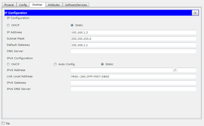
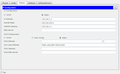
Configure IP Address to the PC's
Step 1 and 2
Step 3
For PC 0
For PC 1


No comments:
Post a Comment